
What Is a Solar PoE Switch?
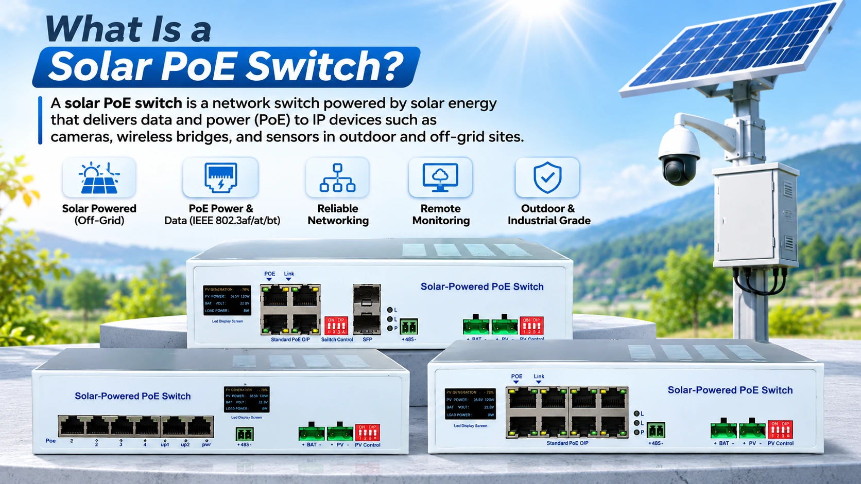
A solar PoE switch is a network switch designed to power Ethernet devices from a solar energy system. It typically combines a solar charge controller, battery management, PoE power output, Ethernet switching, and electrical protection in one device.
This allows equipment such as security cameras, wireless bridges, access points, and IoT terminals to operate at locations without stable grid electricity.
Unlike a standard PoE switch, a solar PoE switch connects directly to a solar panel and battery. Unlike a separate solar controller and network switch, it combines power management and network connectivity in one integrated unit.
How Does a Solar PoE Switch Work?
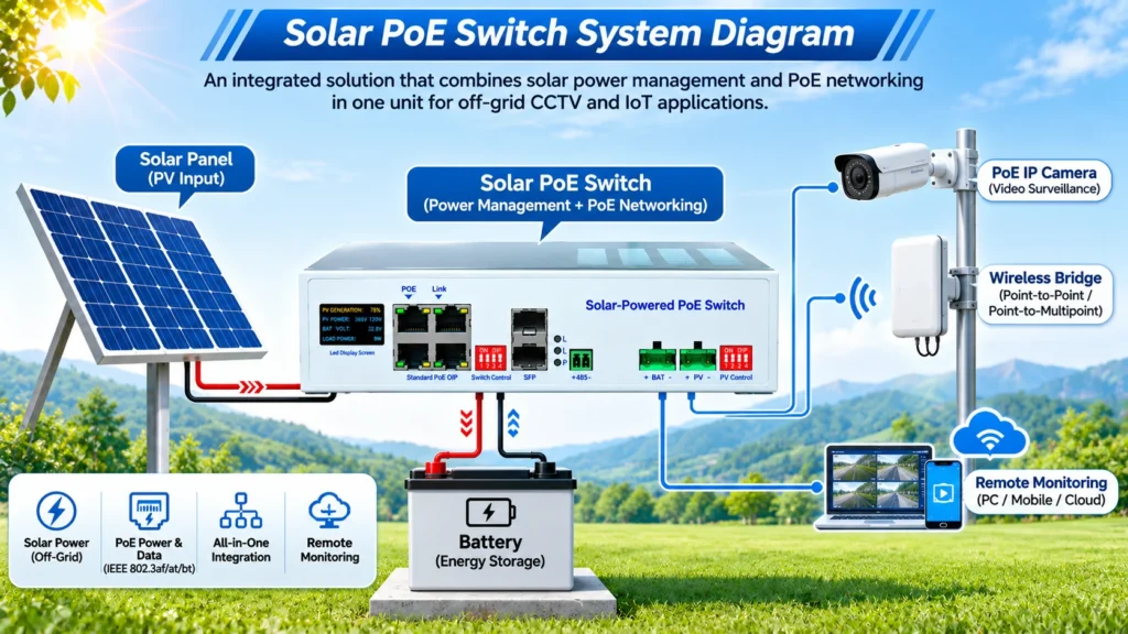
A typical solar PoE system follows this power and data path:
Solar panel → MPPT charging circuit → battery and load management → PoE output → camera or network device
The solar panel generates DC power during the day. The integrated charge controller regulates that energy and charges the battery. The switch then distributes power through Ethernet cables to compatible PoE devices.
At the same time, the Ethernet ports transfer network data between the connected devices and the uplink network.
Depending on the installation, the uplink may use:
- Fiber optic communication
- A 4G or 5G gateway
- A wireless bridge
- A local Ethernet network
- An external IoT or RTU device
A solar PoE switch can provide local power and network switching, but it does not automatically provide an internet connection. A suitable communication backhaul is still required for remote viewing or cloud management.
What Is the Difference Between a Solar PoE Switch and a Standard PoE Switch?
A standard PoE switch normally receives power from an AC or DC power supply. It distributes both data and electrical power through Ethernet cables.
PoE technology allows compatible devices to receive power and data through the same network cable. The exact power level depends on the PoE standard and the connected equipment. Common standards include IEEE 802.3af, 802.3at, and 802.3bt. Cisco explains the basic operation of Power over Ethernet and its standards here.
A solar PoE switch adds the following functions:
| Function | Standard PoE Switch | Solar PoE Switch |
|---|---|---|
| Ethernet switching | Yes | Yes |
| PoE power output | Yes | Yes |
| Direct solar panel connection | No | Yes |
| Battery charging management | No | Yes |
| MPPT charging | Usually no | Often integrated |
| Off-grid operation | Limited | Designed for it |
| Battery protection | External or separate | Integrated or coordinated |
| Solar and load monitoring | Usually no | Often available |
| Remote power control | Model dependent | Model and gateway dependent |
The main value of a solar PoE switch is system integration. It reduces the number of separate devices that must be installed, wired, configured, and maintained at a remote site.
Main Components of a Solar PoE Switch
Solar charge controller
The charge controller manages energy from the PV panel. Many solar PoE switches use MPPT technology to track the panel’s maximum power point and convert the solar input into a suitable charging voltage for the battery.
The controller also helps regulate charging current when solar input is higher than the rated charging capacity.
Battery interface
The battery stores energy for use during the night, cloudy periods, or temporary reductions in solar output.
The correct battery voltage and chemistry must match the switch. Common configurations include 12V and 24V battery systems. Depending on the model, lithium, LiFePO4, lead-acid, gel, or user-defined battery settings may be available.
PoE ports
PoE ports supply power to compatible network devices through Ethernet cables. The number of ports and the output level vary by model.
Possible connected devices include:
- Fixed security cameras
- PTZ cameras
- Infrared night-vision cameras
- Wireless access points
- Wireless bridges
- Network speakers
- Environmental sensors
- Industrial IoT terminals
The number printed on each port is not the same as the total system power budget. For example, four ports rated at 30W each do not automatically mean that the system can continuously deliver 120W in every battery and solar condition.
Uplink ports
Uplink ports connect the local PoE network to another network or communication device. Depending on the model, these may be 100M or 100/1000M Ethernet ports. Some configurations also support fiber communication.
Monitoring and communication interface
RS485 and Modbus communication can be used to monitor battery voltage, charging current, PV input, load status, temperature, and alarms.
An external RTU, DTU, 4G gateway, or other communication module may be required for remote access. Optional networking functions depend on the exact product configuration.
Protection circuits
Solar PoE switches commonly include protection against:
- Battery overcharge
- Battery over-discharge
- PV overvoltage
- PV reverse polarity
- Battery reverse polarity
- Load short circuit
- Load overcurrent
- PoE overload
- Temperature faults
- Reverse current from the battery to the solar panel
Protection functions should always be checked against the exact model manual, especially for lithium battery applications and remote installations.
Solar PoE Switch Types
Solar PoE switches can be classified by their network speed, PoE power level, port count, and application.
100M solar PoE switches
These switches are suitable for basic CCTV, low-bandwidth monitoring, and simple remote network terminals.
A four-port 100M model may be appropriate when the system includes several fixed cameras and does not require gigabit uplink performance.
Gigabit solar PoE switches
Gigabit models are suitable for higher-bandwidth video, wireless backhaul, larger data transfers, and systems that need faster uplink communication.
They may include 100/1000M adaptive ports and support different PoE output levels on different ports.
High-power BT solar PoE switches
BT PoE models are designed for devices with higher power requirements, such as PTZ cameras, infrared dome cameras, wireless communication equipment, or other industrial terminals.
A high-power port rating must still be evaluated together with the total PoE budget, battery voltage, solar input, and expected operating time.
Managed and remotely monitored models
Some solar PoE switches provide status displays, RS485 communication, Modbus protocols, event alarms, or remote load control.
These functions are useful for unmanned sites because technicians can check operating conditions without visiting every installation.<!– IMAGE 2: Insert after “These functions are useful for unmanned sites because technicians can check operating conditions without visiting every installation.” | Visual: Remote solar CCTV site with solar panel, battery enclosure, PoE switch, PTZ camera, and wireless communication link | Alt: “Remote solar PoE switch powering CCTV and wireless monitoring equipment” | Source: company photo or generated visual –>
Documented Solar PoE Switch Configurations
The documented product range includes several configurations for different network and power requirements.
| Model | PoE configuration | Network interface | Solar and battery configuration | Typical application |
|---|---|---|---|---|
| GL-Max342 | 4 × 10/100M 802.3af/at ports, up to 30W per port | 2 × 100M uplink ports | Supports a 300W PV input specification and 12V/24V battery systems | Basic CCTV and low-power remote monitoring |
| GL-Max362 | 2 × Auto PoE ports up to 30W and 2 × BT PoE ports up to 90W | 100/1000M Ethernet ports | Supports a 300W PV input specification and 12V/24V battery systems | Mixed-power cameras and higher-bandwidth networks |
| GL-Max380 | 8 × BT PoE ports, up to 90W per port | 100/1000M Ethernet | Supports a 300W PV input specification and 12V/24V battery systems | Multi-device surveillance and industrial network sites |
For the GL-Max342, the documented total PoE output is lower than the simple sum of the individual port ratings. The GL-Max362 and GL-Max380 also require total PoE budget checks before all ports are used at their maximum stated output.
The final selection should compare:
- Total PoE power budget
- Maximum power per port
- Battery voltage
- Solar panel voltage and current
- Expected daily energy consumption
- Required backup time
- Network speed and uplink type
Where Are Solar PoE Switches Used?
Remote CCTV surveillance
A solar PoE switch can power fixed cameras, PTZ cameras, infrared cameras, and wireless transmission equipment at locations where grid electricity is unavailable.
Typical sites include:
- Roads and highways
- Construction areas
- Forests and nature reserves
- Agricultural land
- Water conservancy facilities
- Mining and petroleum sites
- Perimeter security areas
- Temporary project sites
Wireless communication
Solar PoE switches can power wireless bridges, outdoor access points, and communication terminals. The switch supplies local DC power while the uplink sends data to a control center or network backbone.
Environmental and industrial IoT
Remote sensors and data collection devices can be connected to a solar-powered Ethernet system. RS485 or Modbus communication can also connect the system to an RTU or industrial gateway.
Possible monitoring targets include:
- Water level
- Weather conditions
- Soil and agricultural data
- Environmental parameters
- Equipment status
- Remote infrastructure
Off-grid public and industrial equipment
A solar PoE switch may also be used for public broadcasting, remote lighting control, industrial terminals, and other low-voltage network equipment, provided that the power, network, and environmental requirements are compatible.
What Should You Check Before Selecting a Solar PoE Switch?
1. Device quantity and power consumption
List every connected device and its normal and peak power consumption. PTZ cameras and infrared equipment may draw more power during movement or nighttime operation.
2. PoE standard
Confirm whether each device requires 802.3af, 802.3at, 802.3bt, or a manufacturer-specific passive PoE voltage. Active PoE standards and passive PoE should not be treated as interchangeable.
3. Total PoE budget
Calculate the total expected load instead of adding only the maximum number printed beside each port. The battery voltage, internal conversion efficiency, protection settings, and solar availability all affect the usable output.
4. Solar panel and battery sizing
The solar panel must provide enough energy to operate the load and recharge the battery. Battery capacity must cover nighttime consumption and the expected number of low-sun days.
The project design should consider:
- Daily load energy
- Local solar conditions
- Nighttime operating hours
- Consecutive cloudy or rainy days
- Battery discharge limits
- Camera startup and infrared power peaks
- Cable losses
- Seasonal changes
5. Network architecture
Confirm whether the site needs 100M or gigabit communication, copper or fiber uplinks, a wireless bridge, or a cellular gateway.
6. Environmental installation
Solar equipment installed outdoors may face rain, dust, condensation, heat, cold, lightning, and cable surge exposure. The switch enclosure, cabinet, glands, grounding, and mounting method must match the site conditions.
A product designed for installation inside a protected enclosure should not automatically be treated as a bare outdoor waterproof device.
7. Monitoring requirements
For unmanned projects, RS485, Modbus, local display, alarm reporting, remote restart, and external gateway compatibility can reduce maintenance visits.
Is a Solar PoE Switch Better Than Separate Solar Components?
An integrated solar PoE switch can simplify wiring and reduce the number of separate devices in a remote power and networking system. It is especially useful when the project needs solar charging, battery management, PoE output, and network switching in one installation.
Separate components may still be preferable when the project requires:
- A very large solar array
- Multiple battery banks
- Customized DC voltage conversion
- Special communication protocols
- Independent replacement of each subsystem
- A high-capacity industrial power architecture
The better choice depends on system scale, maintenance requirements, power budget, and the level of customization needed.
Final Answer
A solar PoE switch is an integrated off-grid networking device that uses solar energy and battery storage to provide both Ethernet data and PoE power to remote equipment.
Its main functions are:
- Accepting solar panel input
- Managing battery charging and discharging
- Supplying power through PoE ports
- Switching Ethernet data
- Monitoring system status
- Protecting the PV, battery, load, and network equipment
For remote CCTV, wireless communication, agriculture, water monitoring, environmental sensing, and industrial IoT, the correct model should be selected according to the camera count, PoE standard, total power budget, battery voltage, solar conditions, network speed, and backup-time requirement.
To discuss a solar PoE switch configuration for your application, visit KCEVRA and prepare the device list, power requirements, installation location, battery voltage, solar conditions, and required communication method.